Transduction interference
Definition
Bihant Interference refers to coupling signals (harmonic interference) on one electrical network by conductive media to another.
Effect of
Transduced signal coupling (harmonic interference) on a power network to another electrical network
conduction interference measurement:

Electromagnetic emission (EMI) and electromagnetic sensitivity (EMS) are the main characteristics of measuring electromagnetic compatible (EMC) levels. Electromagnetic emission is tested in turn transmitted emission and radiation emission; electromagnetic sensitivity is also divided into sensitivity and radiation sensitivity. Each of these characteristics should be tested according to different transactions, follow the relevant EMC standards. Here is the measurement of the main characteristics of the test system based on electromagnetic compatibility test.
The measurement of the conduction interference
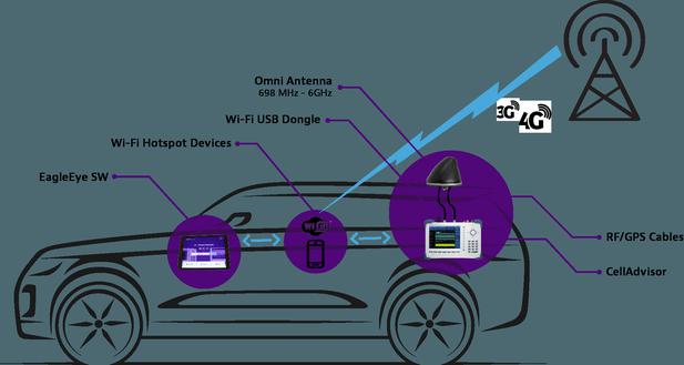
The measurement of the conduction interference is to test the interference of the test device through the power cord or signal line. Therefore, the test object is mainly the input power cord, interconnect and control line, etc. of the EUT. The measurement frequency range is 25 Hz-30 MHz. The test method is mainly the current method and voltage method. This depends on the test object and the frequency band of the test. When measuring the EUT is fed to the conductive interference voltage on the power cord, the power impedance stabilization network (LISN) method in the voltage method can be used. The power impedance stabilization network is added between the grid and the EUT, so that the grid is isolated from EUT, so that the measured interference voltage is only edunted by EUT, and no interference from the grid is not included. And within a predetermined frequency range, a predetermined stable impedance is provided for the conduction interference signal (such as 3825/2 is provided in the 10 kHz to 100 MHz range of 50 Ω) so that the unified and more accurate measurement of the interference voltage can be bound to be referenced. The interconnection of the conduction interference measurement device.
Measurement points
1, correctly set parameters such as bandwidth, frequency range, and limit lines;
2, proper connection and use of LISN and transient signal limits . As before the LISN is connected to the spectrometer, the input / output should be connected to the grid and load. When replacing the grid power supply, the spectrometer power is cut off first. When testing the transient spike, to prevent the spectrometer from being overloaded, it is necessary to add an transient signal limiter at its front end.
3, before testing, the environmental noise level should be checked (detected in the case of EUT power off), which is lower than the limit line 6db in the frequency band required.
4, the measurement should be performed directly through the monitoring measuring end on the LISN. This end is by capacitive coupling, and the power supply line is generated by the interference voltage generated by the EUT and is connected to the spectrometer.
5, turn on the EUT power supply, automatic test, if the displayed spectrum has the line of the limit line, the signal of all the limit lines should be measured again (the limit line is quasi-peak When displayed, then the signal exceeding the limit value is displayed, finding the cause and improvement design.
The measurement of the conduction interference is relatively simple and straightforward. It is not very strict on the measurement site requirements. The range of measurements is mainly low frequency bands, measured results. For the conduction interference spectrum / amplitude characteristics in the range of 150kHz to 700kHz, the limit value is from the VDE-A-CON standard.
Latest: Promote proliferation
Next: Huluzhou Academy


